Product Overview
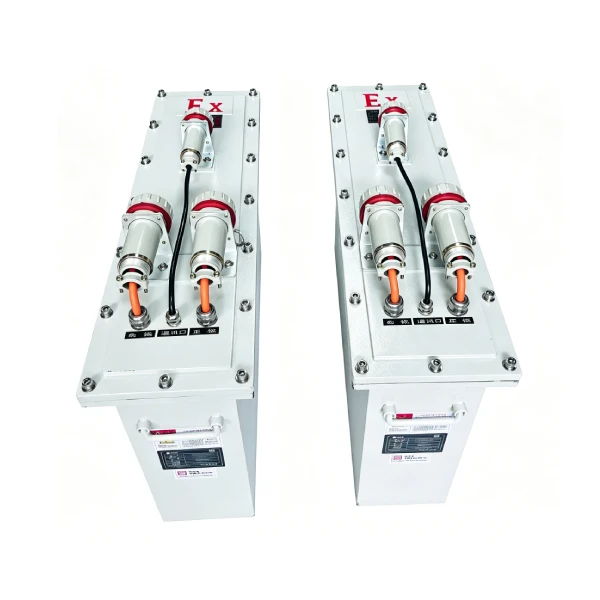
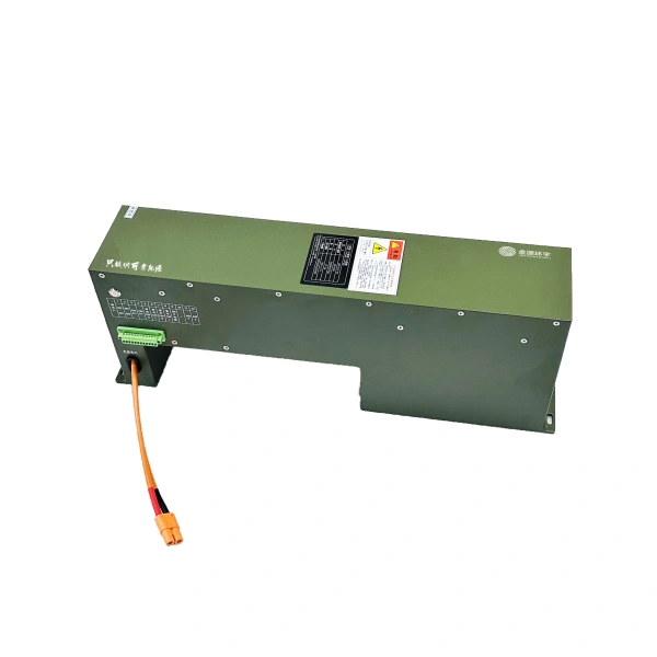
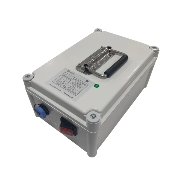
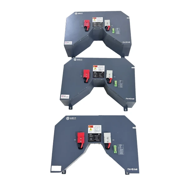
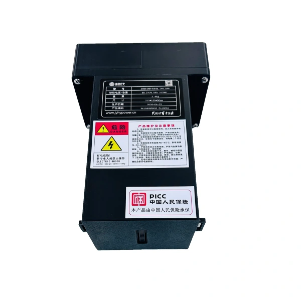
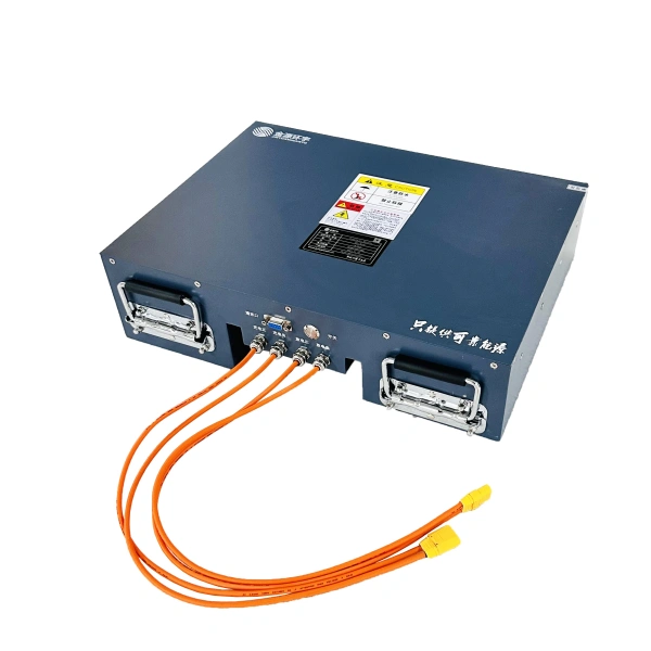
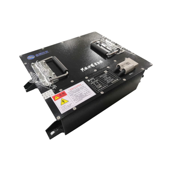
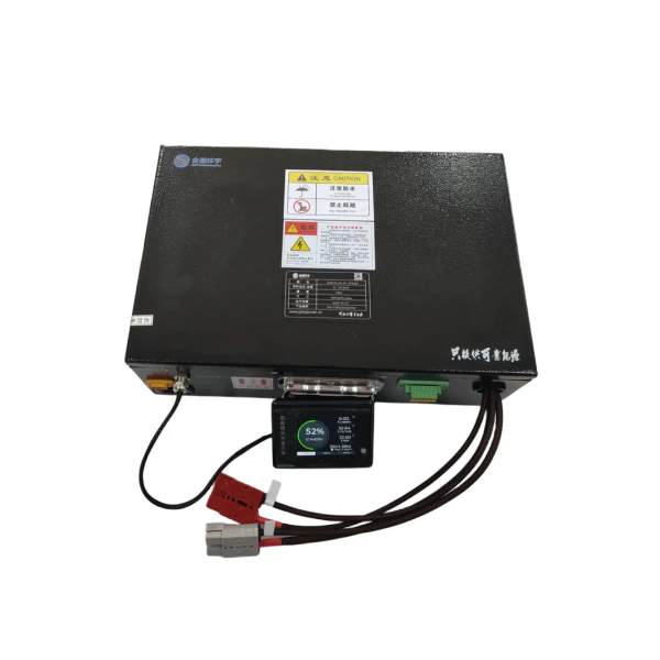
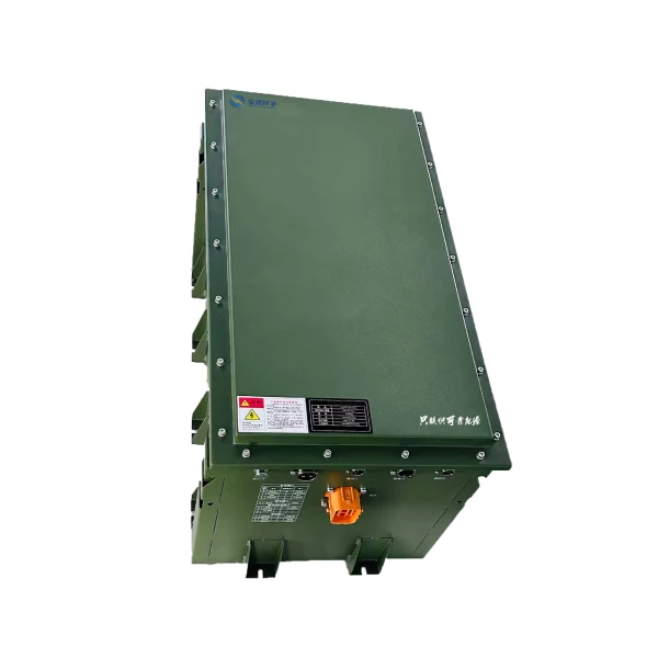
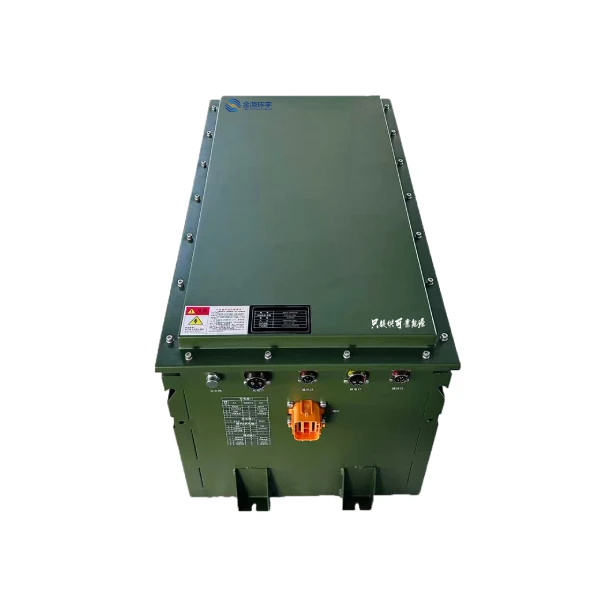
The PK1736 is a high–voltage lithium iron phosphate (LiFePO₄) battery system engineered for heavy–duty industrial and specialised applications requiring sustained high power output. With a nominal voltage of 576V and a configuration of 180 cells in series (180S) , the system delivers 15.55kWh of rated energy.
As industrial equipment continues to evolve toward larger scale, higher intelligence, and greater power demands, 576V high-voltage battery systems have become the preferred power source for heavy-duty AGVs, port automation equipment, unmanned mining trucks, heavy-duty robotics, and specialised vehicles. The high-voltage platform significantly reduces operating current – for example, a 100kW system operating at 72V would draw approximately 1,389A, while at 576V the current drops to just 174A. This reduction delivers tangible benefits: smaller cable cross-sections, lower copper losses, reduced heat generation, improved motor and controller efficiency, extended range, and more stable high-speed operation.
The system is equipped with a high–performance Battery Management System (BMS) featuring 3 CAN communication interfaces (vehicle CAN, charging CAN, internal network CAN), multi–channel voltage and temperature monitoring, passive balancing (≤80mA) , insulation monitoring compliant with GB/T 18384.3-2015, and fault data logging with real–time clock. The BMS operates across an extreme temperature range of -40°C to 125°C and achieves cell voltage sampling accuracy of ≤±3mV.
The battery enclosure is rated IP67 for dust and water ingress protection, making it suitable for harsh industrial environments.
Technical Specifications
Communication & Interface
The PK1736 is equipped with three independent CAN communication channels:
| Channel | Function |
| Vehicle CAN | Integration with vehicle/equipment control system – 250kbps |
| Charging CAN | Communication with DC fast charger – 250kbps |
| Internal Network CAN | Communication between BMS master and slave modules – 250kbps |
Additional features:
- Daisy–chain communication between BMU modules
- 4 high–side and 4 low–side signal inputs
- PWM bidirectional control
- 8 high–side driver outputs (≤1A/12V) for relay control
- CP (Control Pilot) wake-up for charging activation
Key Application Areas
Heavy-Duty AGV & Port Automation
576V high-voltage battery systems are increasingly deployed in heavy–duty AGVs, port container transporters, and automated terminal equipment. The high voltage platform enables these large-scale vehicles to operate with lower current draw, reducing heat generation and improving overall system efficiency during continuous, high-load operations. Typical applications include port unmanned transport vehicles, automated container transporters, and heavy-load RGV (Rail-Guided Vehicle) systems.
Mining & Underground Equipment
The PK1736 is well-suited for mining locomotives, underground transport vehicles, and tunnel boring equipment. Mining applications demand high reliability, robust construction, and the ability to deliver sustained power over long duty cycles. 576V battery systems are widely used in coal, metallurgy, and mining industries for narrow-gauge railway traction and underground transport. The IP67-rated enclosure ensures protection against dust and moisture commonly encountered in mining environments.
Electric Buses & Commercial Vehicles
576V is a standard voltage platform for electric buses, heavy trucks, and commercial vehicles. The high-voltage architecture enables more efficient power delivery, extended range, and compatibility with high-power DC fast charging infrastructure.
Electric Vessels & Marine Applications
576V battery systems are increasingly adopted in electric ferries, workboats, excursion vessels, and other marine applications. Marine applications require high reliability, salt-fog resistance, and the ability to deliver sustained power over extended periods. Real-world deployments include passenger ferries with 576V systems and electric excursion boats with capacities exceeding 500kWh.
Large-Scale Energy Storage Systems
576V high-voltage battery systems serve as the core storage medium for commercial and industrial (C&I) energy storage systems, microgrids, and high–power UPS applications. The modular architecture allows for flexible capacity scaling, making it suitable for grid-tied commercial solar installations, manufacturing facility backup power, and data centre UPS systems.
Defence & Specialised Platforms
576V battery systems are also deployed in military ground vehicles, unmanned defence platforms, and specialised mission–critical equipment. These applications demand extreme reliability, wide operating temperature ranges, and compliance with stringent military standards. The PK1736’s BMS operates from -40°C to 125°C, supporting operation in extreme environments.
BMS Control Strategy
Low-Voltage Power-Up Strategy
Power–on: Vehicle 12V DC power supply energises and wakes the BMS
Power–off: Vehicle 12V DC power supply removed; BMS shuts down after 3s delay
High-Voltage Power-Up & Power-Down Strategy
Power–up sequence:
- BMS detects vehicle 12V DC power and activates
- Self-diagnosis performed – if normal, waits for high-voltage enable command
- Upon receiving enable command, pre-charge relay closes for pre-charging
- After successful pre-charge, main positive relay engages – system enters discharge mode
Power–down: BMS detects loss of 12V DC power and initiates normal shutdown
DC Fast Charging Strategy
Charging activation: BMS self-diagnosis completes with no faults; upon receiving charging command, charging relay engages and charging begins
Charging termination:
- BMS detects severe battery fault, OR
- BMS detects battery fully charged (SOC calibrated to 100%)
Charging profile:
- Constant current charging until highest cell voltage reaches ≥3.6V
- Switches to constant voltage mode (linear current reduction)
- Continues until current drops to 0.1C, then maintains 0.1CStops when highest cell voltage reaches 3.65V; SOC set to 100%
Thermal Management Strategy
Charging heating:
- When Tmin ≤ 0°C: heating relay engages, charging relay disengages – heating mode
- When Tmin > 0°C: charging relay engages, heating relay disengages – charging mode
Discharging heating:
- When Tmin < -20°C: heating relay engages – discharge heating mode
- When Tmin > 0°C: heating relay disengages – normal discharge mode
SOC Calibration Strategy
Before calibration, SOC displays 99% (not 100%)
Calibration to 100% occurs when highest cell voltage ≥3.65V
SOH Estimation Strategy
SOH is determined based on charge/discharge cycle count:
| Cycles | SOH (%) |
| ≤50 | 100 |
| 400 | 97 |
| 1000 | 92 |
| 1500 | 88 |
| 2000 | 87 |
| 3000 | 81 |
Fault Alarm & Protection Levels
The BMS implements a 3-level fault alarm system (Level 3 is most severe):
| Level | Response |
| Level 1 | Alarm only – no power limitation |
| Level 2 | Power limitation to 50% of maximum allowed |
| Level 3 | Power set to 0, forced power-down after 30s (requires BMS reboot to clear) |
Key protection thresholds include:
| Fault | Level 2 Threshold | Level 3 Threshold |
| Cell Over-voltage | 3.7V (50% power) | 3.75V (0 power) |
| Cell Under-voltage | 2.7V (50% power) | 2.0V (0 power) |
| Cell Imbalance | 0.4V (50% power) | – |
| Battery High Temp | 55°C (50% power) | 60°C (0 power) |
| Battery Low Temp | –30°C (alarm only) | – |
| Charge/Discharge Overcurrent | – | 50A (0 power) |
| Insulation Fault | 500Ω/V (50% power) | 100Ω/V (0 power) |
Why Choose High-Voltage (576V) Systems?
100kW at 576V draws only 174A vs 1,389A at 72V
Smaller cable cross-sections – lower cost and weight
Reduced copper losses and system heating
Improved motor and controller efficiency
More efficient power delivery – longer operation
Stable performance at high speeds
Supports high-power DC fast charging
Notes & Warnings
- This is a high–voltage system (576V nominal, up to 657V) – strict safety protocols must be followed during installation, maintenance, and operation.
- Insulation monitoring is integrated; the system monitors insulation resistance continuously and reports faults at three severity levels.
- HVIL (High–Voltage Interlock) should be implemented in the overall system design to ensure safe disconnection.
- Use only the specified charger with correct voltage and current parameters.
- Charge only when battery temperature is within the permitted range.
- Do not over–discharge – recharge promptly after full discharge.
- For storage exceeding 2 months, maintain at ~50% SOC.
- Storage voltage per cell: 3.2–3.35V.
- Do not connect batteries in series without proper engineering assessment.
- Level 3 faults require BMS reboot to clear.
Ordering Information
For customisation (different capacity, voltage, connectors, communication protocols, or application-specific requirements), please provide your application details – including load profile, duty cycle, ambient conditions, and desired interface. Engineering support is available for tailored solutions.
For further technical data or to request a sample, please contact our sales team.