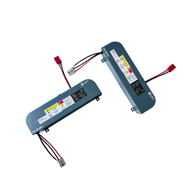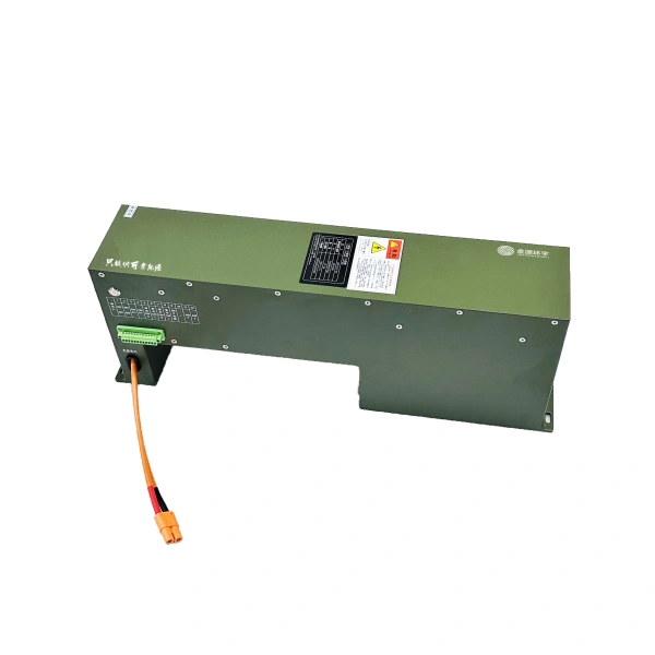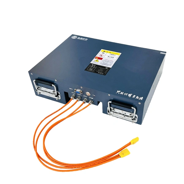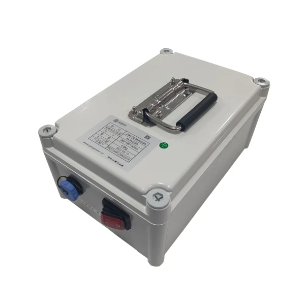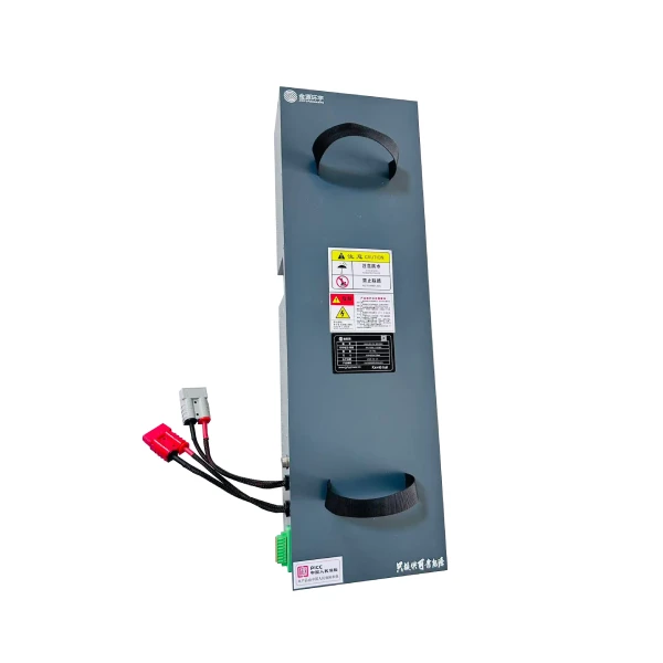
Product Overview
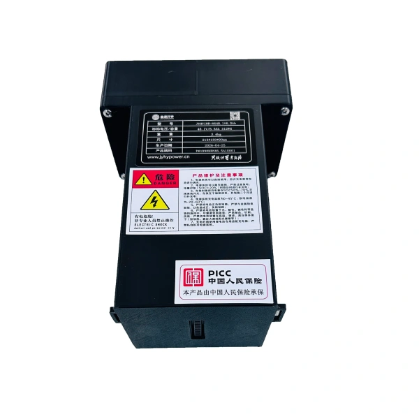
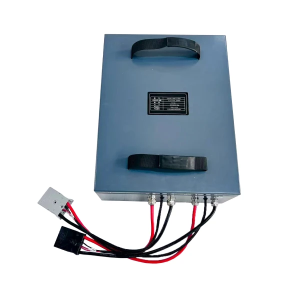
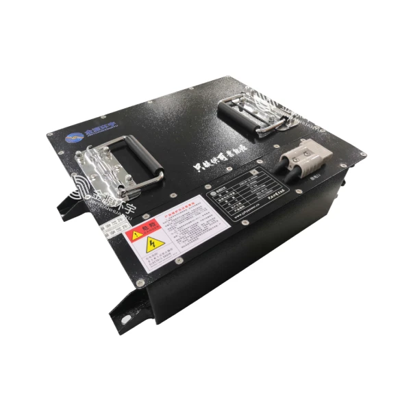
The PK1302A1-01 is a 48V / 45Ah low-temperature power battery pack built from 3.2V / 15Ah lithium iron phosphate (LiFePO4) cells in a 3P15S configuration. The pack delivers a nominal voltage of 48V with a rated capacity of 45Ah and a minimum capacity of 43Ah, and is documented as an AGV on-board power-type lithium-ion battery developed against customer requirements.
The pack is certified-ready for the European market: an IEC 62619 test report is available for this model (see the dedicated Certification section, where certificate number, issuing laboratory and scope of coverage are listed). Together with the integrated charge heating logic, the certification allows the pack to be deployed in EU industrial and cold-store AGV projects.
The system is managed by a Battery Management System (BMS) that continuously acquires the pack’s charging, discharging, over-current, short-circuit and temperature conditions in real time and applies protection according to preset thresholds. The LiFePO4 cells adopt an advanced production process, giving the pack good cell consistency, high specific energy, long service life, safe and reliable operation and a wide operating temperature range.
A dedicated thermal management function is integrated for sub-zero operation: below 0 degC the heating system starts and charging is suspended until the pack reaches a safe temperature. This introduction describes the pack’s outline dimensions, characteristics, technical specifications and handling precautions, based on document PK1302A1-01 (Version V1.0, issued 2025-02-11).
Certification – IEC 62619
The PK1302A1-01 is supported by an IEC 62619 test report. IEC 62619 is the international safety standard for secondary lithium cells and batteries used in industrial applications, and a valid test report is a prerequisite for battery packs placed on the EU industrial and mobile-robot market. The report is held by the manufacturer and is available to customers and integrators on request.
The items below summarise the certification status. Entries marked [TO BE CONFIRMED] are not stated in the current product specification and must be verified against the issued report before being quoted in tenders, declarations of conformity or customer documentation.
| Standard | IEC 62619 (safety requirements for industrial secondary lithium cells and batteries) |
| Test report status | Available for this model; copy obtainable from the manufacturer on request |
| Report number | [TO BE CONFIRMED] |
| Certificate number | [TO BE CONFIRMED] |
| Issuing laboratory / test house | [TO BE CONFIRMED] |
| Scope of coverage | [TO BE CONFIRMED] – cell level or battery pack level |
| Applicable model(s) | PK1302A1-01 |
| Issue date | [TO BE CONFIRMED] |
| Validity / expiry | [TO BE CONFIRMED] |
| Accreditation mark on report | [TO BE CONFIRMED] |
Technical Specifications
| Parameter | Value | Remark |
| Model | JYHYLFP-GX-48V45Ah | LiFePO4 power battery pack |
| Nominal Voltage | 48V | 15 cells in series |
| Rated Capacity | 45Ah | @0.3C (3A), 25 degC |
| Minimum Capacity | 43Ah | @0.3C (3A), 25 degC |
| Cell Model | JYHYIFP-15Ah | 3.2V / 15Ah prismatic cell |
| Configuration | 3P15S | Stated in the datasheet as 30 cells in total (see Notes) |
| Standard Charge Current | 30A | – |
| Charge Cutoff Voltage | 54.75V | Max. 3.65V per cell |
| Standard Discharge Current | <= 60A | – |
| Discharge Cutoff Voltage | 39V | Min. 2.6V per cell |
| Standard Equalizing Charge Time | ~1.5h | – |
| Continuous Discharge Current | 35A | – |
| Max. Continuous Discharge Current | 55A | 15 degC – 45 degC, <= 60s |
| Peak Discharge Current | 80A | 15 degC – 45 degC, <= 1s |
| Communication | RS485 | Default protocol, 115200 bps |
| Communication Connector | Pin 1 KEY+ / Pin 2 KEY- / Pin 3 Vehicle 485-B / Pin 4 Vehicle 485-A / Pin 5 Debug 485-B / Pin 6 Debug 485-A / Pin 7 Forced charge + / Pin 8 Forced charge – | 8-pin bulkhead terminal |
| Charge Port | Anderson 50A grey, 4mm2 EV power cable, 150mm flying lead with braided sleeve | – |
| Discharge Port | Anderson 50A red, 6mm2 EV power cable, 150mm flying lead with braided sleeve | – |
| Charging Method | 54.75V / 30A dedicated LiFePO4 charger | Max. charge voltage 54.75V, configurable |
| Enclosure | Sheet metal Q235, Alpine Blue | – |
| Dimensions (L x W x H) | 650mm x 200mm x 118mm (+/-1mm) | Excluding handle and connectors |
| Weight | ~20kg | – |
| Operating Temperature (CC/CV) | Charge: -15 degC to 55 degC Discharge: -15 degC to 55 degC Storage: 0 degC to 45 degC | Extreme temperature limits apply |
| Low-Capacity Shutdown | Forced shutdown at 10% SOC | Prevents deep over-discharge |
| Charge Heating Logic | Provided | See Heating Control Logic section |
| Product Configuration | User manual, certificate of conformity, product specification, inspection report | – |
| Supplied Accessories | Anderson 50A grey 2 sets (1 pair) / Anderson 50A red 1 set / 1m 4G harness | – |
Heating Control Logic
The pack cannot be charged below 0 degC. A thermal management system with dedicated heating control logic is integrated; in charging mode the logic operates as follows:
- When the lowest detected cell temperature (Tmin) is below 0 degC, the heating system starts and heats the pack. Charging is not performed during this phase.
- When Tmin reaches 5 degC or above, heating stops and the pack is charged only.
- If the heating system has not been activated and the detected temperature is between 0 degC and 45 degC, normal charging is permitted. In this condition the heating relay must not be closed. Discharging is not heated, and discharge is permitted above -20 degC.
Tmin is defined as the lowest temperature detected by the battery pack.
BMS Protection & Monitoring
The BMS is the circuit system that safeguards the safe and reliable operation of both individual cells and the assembled pack. It samples the pack’s total voltage, individual cell voltages, state of charge, charge/discharge current and battery ambient temperature, monitors the charging and discharging process and status, and provides effective protection and alarm functions. The system typically comprises acquisition circuitry, monitoring and protection circuits, electrical and communication interfaces, thermal management and data transmission.
An over-discharge protection mechanism is built into the system, complemented by a forced-charge switch in the design. A low-capacity alarm triggers a forced shutdown at 10% SOC to prevent deep over-discharge. BMS sampling accuracy is not stated in the specification (see Notes).
Communication & Data Monitoring
The pack provides RS485 communication using the manufacturer’s standard protocol at a default baud rate of 115200 bps, reporting at least the following items:
Charge/discharge status, state of charge (SOC), output voltage, output current.
Pack temperature, ambient temperature, PCB temperature, individual cell temperature.
Pack charge over-voltage, charge over-current, discharge under-voltage, reverse polarity, discharge over-current, pack high temperature, ambient high temperature, low capacity, temperature / voltage / current sensor failure, and cell-level high temperature, charge over-voltage, discharge under-voltage, charge over-current and discharge over-current alarms and protections.
The 8-pin bulkhead connector additionally provides KEY+/KEY- switching, a separate debug RS485 channel and forced-charge terminals, enabling service diagnostics without disturbing the vehicle bus.
Key Features
The PK1302A1-01 is supported by an IEC 62619 test report, facilitating access to the EU industrial battery market. Certificate number, issuing laboratory and scope of coverage are listed in the Certification section.
Integrated thermal management heats the pack below 0 degC and permits charging only once Tmin reaches 5 degC, enabling reliable cold-store and outdoor winter operation.
Lithium iron phosphate cells deliver high safety, long service life and stable performance across a wide temperature range.
35A continuous, 55A maximum continuous (<=60s) and 80A peak (<=1s) discharge support AGV acceleration and lifting duty cycles.
Status, environmental and alarm data are available to the vehicle controller for intelligent energy management and fault diagnosis, at 115200 bps.
Separate vehicle and debug channels simplify commissioning and after-sales service.
Forced shutdown at 10% SOC protects the pack from irreversible over-discharge damage.
650 x 200 x 118mm sheet-metal Q235 housing at approximately 20kg suits under-deck AGV installation.
Operating Conditions
| Condition | Range |
| Charging | -15 degC to 55 degC (heating required below 0 degC) |
| Discharging | -15 degC to 55 degC |
| Storage | 0 degC to 45 degC (optimum 15 degC – 25 degC, dry conditions) |
| Operating Environment | Indoor use, -15 degC to 55 degC, relative humidity (65 +/- 20)% |
| Storage Voltage | 3.2V – 3.35V per series cell |
Typical Applications
AGV and AMR platforms operating in cold-store, chilled and outdoor winter environments
Intelligent logistics and material-handling equipment requiring 48V-class power
Industrial mobile platforms with low-profile under-deck battery bays
EU-market projects requiring an IEC 62619 test report as part of the technical file
Why Choose This Battery?
Simplifies EU market access and customer technical-file review
Reliable charging and operation in sub-zero cold-chain environments
High safety and long service life with stable thermal behaviour
Supports demanding AGV acceleration and lifting duty cycles
Fast commissioning and simplified field diagnostics
Protects the pack from deep-discharge damage
Fits low-clearance AGV chassis
Wide temperature window without derating for most indoor and cold-store duties
Notes & Warnings
- Certification: the IEC 62619 test report is stated to be available for this model, but the report number, certificate number, issuing laboratory, scope of coverage (cell or pack), issue date and validity are NOT stated in the specification. All such fields are marked [TO BE CONFIRMED] in the Certification section and must be verified against the issued document before publication.
- Cell count discrepancy: the specification table states a 3P15S configuration and ’30 cells in total’. A 3P15S arrangement requires 45 cells; the stated total of 30 cells is inconsistent and is reproduced here as published, without correction.
- Serial numbering: item numbers 16 and 17 appear twice in the specification table (charge port / discharge port, then communication / charging method). The values are reproduced as published.
- Discharge temperature: the specification table states a discharge range of -15 degC to 55 degC, whereas the heating logic section states that discharge is permitted above -20 degC. Both values are reproduced as published; confirm the applicable limit for the intended duty cycle.
- Charge temperature: the specification table and section 5.1.3 state -15 degC to 55 degC, while the heating logic states that charging is not performed below 0 degC and section 8.1 prohibits charging below -15 degC. The pack must not be charged below 0 degC without the heating system having raised Tmin to 5 degC.
- Storage temperature: the specification table writes ‘0 degC to 45 degC’ in a form containing a stray minus sign (‘-0 degC’). The value 0 degC to 45 degC is used in this document.
- Storage interval: section 5.3.13 refers to packs unused for more than three months, while section 6.1 refers to storage longer than one month. Both thresholds are reproduced as published.
- Not stated in the specification: ingress protection rating (IP class), BMS sampling accuracy, cycle life, energy density, UN38.3 test summary and CE marking. No values are assumed in this document.
- Charge current must not exceed 30A; charge voltage must not exceed 54.75V; continuous discharge current must not exceed 35A.
- Do not reverse-charge. The system has reverse-connection protection, but reversed polarity will destroy the pack and create a safety hazard.
- Do not over-discharge. Switch the pack off after use, recharge within 24 hours after a full discharge, and keep the voltage above 48V during long idle periods.
- The pack voltage exceeds the 36V human safety threshold – never touch the positive and negative terminals with the body directly.
- Use only the dedicated 54.75V / 30A charger. Do not charge for extended periods after the pack is full; disconnect the charger.
- Do not connect packs in series or parallel; do not disassemble, crush, drop, nail-pierce or weld the pack; never short-circuit the terminals.
- Keep away from heat sources, fire, water and direct sunlight; store in a dry, ventilated indoor place away from other hazardous materials.
- For storage longer than three months, keep the pack at approximately 50% SOC: charge at 0.3C until the pack voltage is above 48V, switch the pack off, then store it under the recommended conditions.
- For long-term storage, charge the pack for 2 hours every two months.
- Stop charging immediately if a high-temperature warning or a single-cell over-voltage warning is reported. Charge immediately when a low-capacity alarm appears; over-discharge is strictly prohibited.
- Before use, inspect the package and the pack for damage, leakage or missing accessories, and verify terminal polarity and voltage.
Ordering Information
For customisation – capacity, voltage, connectors, communication protocol, heating requirements or other application-specific needs – please provide your application details, including load profile, duty cycle, ambient conditions and desired interface. Engineering support is available for tailored solutions. A copy of the IEC 62619 test report and the full technical file can be supplied with the quotation on request.
For further technical data or to request a sample, please contact our sales team.